How to Use Transistor as Relay Circuit Diagram The Transistor relay driver circuit helps control high-power devices using a low-power signal. It is widely used in home automation, industrial controls, and automotive electronics. Its primary function is to use a small input signal to activate a relay (5V, 6V, or 12V), which can then switch on bigger loads like motors, lights, or other high-current devices. Components List The following

How to increase the gain Figure 4 is the relay driver circuit that has increasing gain up. In case that very low input current from a digital circuit. We will see that this circuit we use the transistor as a Darlington compound to replace two transistors. In this post we learn how to design and buld a simple transistor relay driver circuit by correctly calculating the transistor driver circuit. Circuit Design of 12V Relay Driver using Transistor as a Switch About This Video:- A relay is an electromagnetic switch operated by a relatively small electric current that can turn on or off a

Transistor Relay driver circuit in digital Circuit Diagram
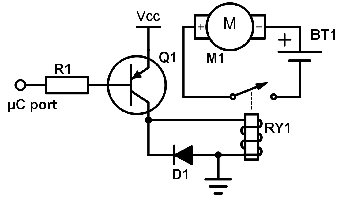
This video will show how to make a relay driver circuit or simple relay driver or how to use relay .It will provide the complete connection diagram and explanation of the circuit. During the transition of light/temperature levels, the relay clicks which may cause sparking of contacts. By using a simple tip, this problem can be avoided. Below is the circuit of a relay driver using the NPN transistor BC 548. The relay is connected between the positive rail and the collector of the transistor.
A pretty good deal for the microcontroller. How a Relay Driver Circuit Works The bipolar transistor based driver circuitry makes use of the transistor´s cutoff and saturation mode to control the relay. In other words, the transistor is used as a ¨switch¨.

How to Make 12V Relay Driver Circuit using Transistor Circuit Diagram
For reasons that have little to do with the static calculations in the other answers, I would use a beefier transistor such as the 600mA 2N4401 or a MOSFET. Switching an inductive load is harder on the transistor than switching a resistive load, even with the diode. At some point the full relay coil current is flowing through the transistor for a short period of time with more than 12V across An electronic circuit will normally need a relay driver using a transistor circuit stage in order to converter it's low power DC switching output into a high power mains AC switching output.