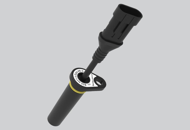
Rotating speed sensors based on Hall effect Circuit Diagram analysis speed measurement module. The speed data can be obtained through counting impulse signals and displayed on LED. Experience shows that the system have high stability, it can meet the needs of DC motor speed measurement. Keywords: Hall sensor; DC motor; speed measurement; control system. 1 Introduction DC motor has been widely used in A Hall-effect sensor varies its output voltage in response to a magnetic field. Hall-effect devices are used as proximity sensors and for positioning, The carrier speed is the result of a statistical measure, and non-linear effects of the magnetic field can alter the results obtained experimentally. Therefore, a correction term rh is Hello, I am trying to measure the speed of a bicycle wheel using a hall effect sensor. I am using the code below and get the RPM which I then convert into m/s. However, I want the measurement to be more accurate. Using my code the RPM changes by 60 which is roughly 2 m/s. I want a more accurate speed measurements with not such big intervals
.jpg)
This voltage can be converted into position or distance measurements. For example, in automotive applications, wheel speed sensors use Hall Effect sensors to measure wheel rotation speed accurately; Switching Behavior: Switch-type Hall Effect sensors produce digital outputs that change state when a specific magnetic field threshold is reached

Calculate Speed using Hall effect sensor Circuit Diagram
This project uses a Hall effect sensor to detect the presence of a magnet. Whenever a magnet moves past this sensor, it can detect it. This sensor can be used to do a lot of different things. For instance, if we need to detect a door closing; then we simply have to attach a magnet to the door and a hall sensor to the frame of the door.

We will be using the Hall effect sensor and a magnet to find the number of times the car wheel rotated in a minute.The sensor and magnet will be placed in a such a way that at a particular point in every rotation of the wheel the sensor will detect the magnet. One of the draw backs of this code is that the first measurement of speed is I've decided to upgrade the car with RPM measurement using Hall sensor and a neodymium magnet. In the following steps I'll describe the parts needed for the setup and will provide the code. I also use the IR remote to change speed of the motor (I change the PWM signal +/-20) to check if the code and the setup is working.

Motor Speed Control Using Hall Circuit Diagram
Motor speed meter, hall sensor & oscilloscope HackIn this video we show you how you can measure any motor rotational speed using hall sensor and oscilloscope

Hello, hope you are well. I have a project in electronics in which I need to measure the rotational speed of a fan using a hall effect sensor and display this speed on a 16x2 lcd. I have no problem with the display on the LCD. But I don't know how to go about it with the hall effect sensor to be able to measure the rotational speed of a fan. Hello all, hope you're doing well. I got a brushless motor with 3 Hall sensors inside it. It is 3-phase motor and I want to write a code to calculate the speed in RPM of the motor. I know that using the hall sensors, the speed can be calculated, but I'm new and I don't know how to read the hole sensors and do the calculations. I appreciate any advice or help! I have connected the 3phase and
